
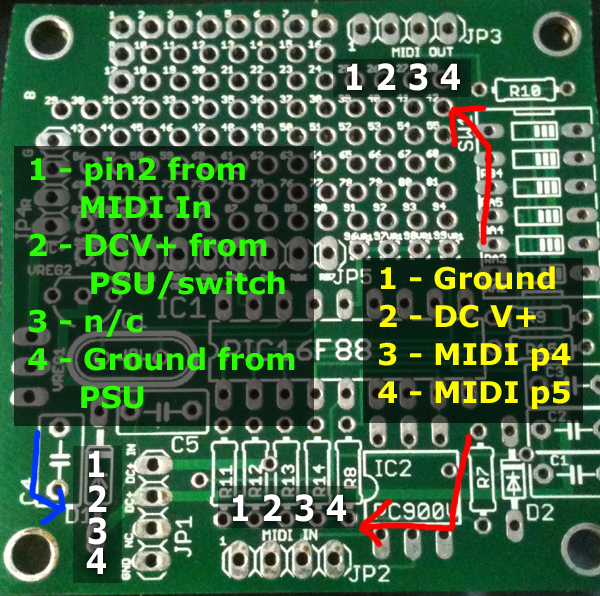
JP1 is the power connector:
Pin1) This is connected to Pin2 of JP2 which is DC+ from power over MIDI.
Pin2) This is the DC+ input to the board, 12 to 15V is ideal.
Pin3) Is not connected
Pin4) Is ground
-If you only want to use power over MIDI, wire pins 1 and 2 together.
-If you only want to use a wall wart power supply, wire the positive terminal of your power jack to pin 2 and the ground terminal to pin 4.
-If you want to use a switch between a wall wart and power over MIDI, wire the negative terminal of your power jack to pin 4, the positive terminal to one side of your switch, pin 1 of JP1 to the other side, and pin 2 to the center of your switch.
JP2 and JP3 are MIDI in and out:
Pin 1) Ground for power over MIDI (MIDI pin 1)
Pin 2) DC+V for power over MIDI (MIDI pin 3) (on JP3 this is switched on/off by pin 6 of the dipswitch)
Pin 3) MIDI pin 4 (data).
Pin 4) MIDI pin 5 (data).
This is the MIDI electrical specification if you need clarification on which MIDI pins this refers to.
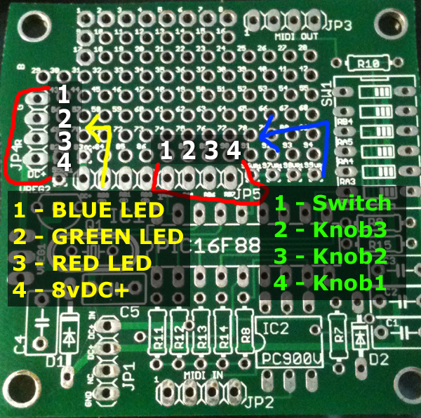
JP4 is the LED connector:
Pin 1) Blue LED cathode (-)
Pin 2) Green LED cathode (-)
Pin 3) Red LED cathode (-)
Pin 4) Common anode for all (+). Fed 8vDC+ from LM7808 on the mainboard.
JP5 is the external switch/knobs connector:
Pin 1) External switch (alternates what the knobs do, 3 banks described below)
Pin 2) Knob 3 (Master level, blue osc, blue level)
Pin 3) Knob 2 (Strobing, green osc, green level)
Pin 4) Knob 1 (Color Osc, red osc, red level)